Using the ESP8266 WiFi Module with Arduino Uno publishing to ThingSpeak
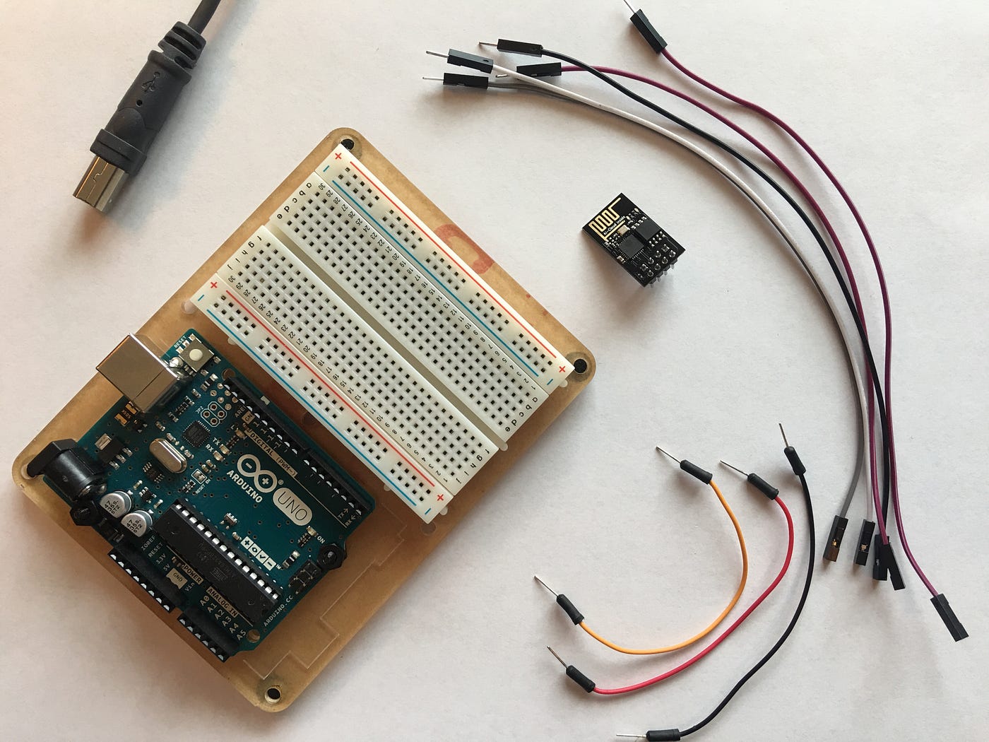
I’ve got this ESP8266 WiFi module hanging around that I’ve never really used. I also have a few Arduino UNOs sitting here not getting any use at the moment. I thought this would be a great time to put the two together for a project I’m working on. It wasn’t easy. There was a ton of conflicting and confusing content that made it much more difficult. I’m writing this up in hopes it might help the next guy just a little bit.
Contents
- Understanding the ESP8266
- Setting up ThingSpeak
- Testing the ESP8266 Directly
- Accessing ESP8266 from Arduino Uno code
- Putting it all together
Understanding the ESP8266
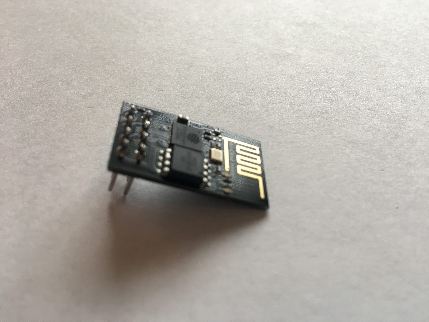
First and foremost, a search for ESP8266 will turn up many references to an awesome tiny micro-controller that’s been all the rage until the new ESP32 recently came out. At first, you might think you searched for the wrong thing, but nope you didn’t. This little component is the original and it technically can be programmed just like it’s bigger siblings. It only has two GPIO pins though and isn’t really designed to be a micro-controller. Adding “Wifi Module” to your searches helps focus the results
Search for “ESP8266 WiFI Module”
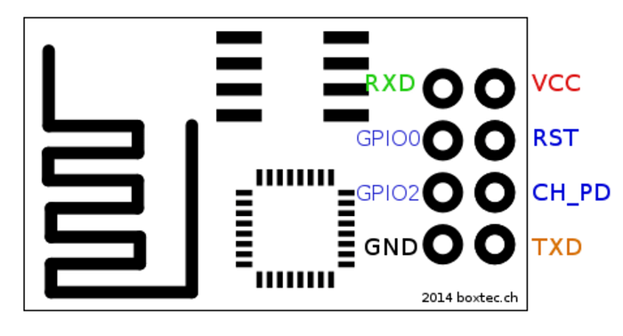
Next, we have the Pinout connections. Depending on the article you’re looking at the connections will change. It’s important to understand the pins and how they’re used. In general, you have a VCC for power and your common GND. You also have TX and RX to transmit and Receive. You have two GPIO pins, a reset pin, and a CH_PD pin. This board is designed to be an add-on to another micro-controller and offers a feature for being able to turn it on or off by setting the CH_PD pin from High to Low. In my case, I’m going to leave it on all the time so I’m just pulling high all the time.
CH_PD is a chip controlled power down and needs to pull high in order to run
Speaking of voltage, all the articles I’ve seen warnings not to give it too much power, but mine seemed to need more than the 3.5v Arduino served up. In my tests, the module wouldn’t start up correctly with 3.5v which made it very difficult to debug early on. I ended up switching to the 5v pin and everything has been great.
NOTE: The ESP8266 maximum working Voltage is 3.6V.
It’s supposed to run with less but mine didn’t. The most common responses to this article scream not to use 5v. While it worked for me, use caution.
If 3.5v is not enough, consider more
Accessing the ESP8266 WiFi Module is also confusing. There are two main concepts here. In the first option, you’re using the Module as an add-on and writing code in the Arduino to talk to it. The other model is that you’re trying to work on the module directly to program it or upgrade it. For our final project here we will have code on the Arduino talking to the module, but to make sure everything is working we’ll be talking to the Module directly (kind of). More on that later.
Understand if you’re accessing the Arduino Uno or the ESP8266 Module
Setting up ThingSpeak

Let’s take a moment to create an endpoint we can send some data to in our test.
- Create an account on ThingSpeak https://thingspeak.com/
- Create a new channel with one field label
- Get the API Key
- Review the “Update a Channel Feed” Url
ThingSpeak is insanely easy to use. Once you have your channel and key you can simply make an HTTP request to https://api.thingspeak.com/update?api_key=YOUR_KEY_HERE&field1=4 to send the value 4 into field1. Try it in your browser, then review the data in the Private View of your channel.
Make note of the channel’s API Key to use later in your code
Testing the ESP8266 Directly
OK so now that we have something to test against, let’s get back to the ESP8266. Remember we left off noting that you can access the WiFi module with Arduino Code or directly. I’m a fan of reducing variables and since I didn’t trust the code samples I was finding, I thought it best to make sure my WiFi Module was working by itself before trying to tie it into the Arduino code. PROBLEM you need special adapters to connect it to your computer. A USB Serial TTY adapter might work, but I didn’t get the wiring right and almost fried the module. SOLUTION use the Arduino Uno as a Bridge, bypassing everything in the Uno and talking to the module directly.
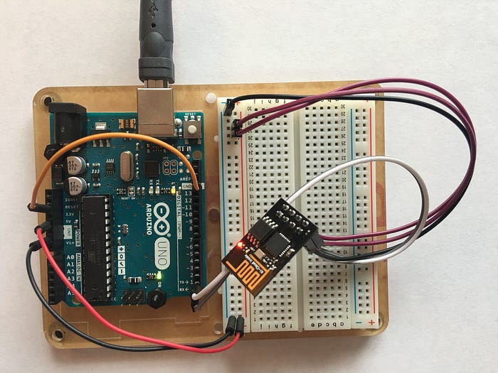
So here’s how this works. You can connect the reset pin on the Uno to GND to bypass the Arduino bootloader. This allows you to connect to the Uno’s TX and RX from the Module. Since the Uno’s USB cable is properly hooked up to the Uno’s TR and RX, any signals put on those lines will pass right on to the module. Here’s the trick, in this case, we want the TX on the Uno to connect to the TX on the module and the RX from the Uno to the RX on the Module. Realize that all we’re doing here is extending the TX line into the module. The crossover, in this case, is already managed in the USB adapter. We’ll change this later. Only in this bridge model do you have TX to TX and RX to RX.
Use the Uno as a bridge to talk to the module directly. Bypassing the Uno boot loader connecting RESET to GND, then connect TX to TX, RX to RX, GND to GND, VCC and CH_PD to 5v.
Wiring
Esp8266 | Arduino
-----------------
     RX | RX
     TX | TX
    GND | GND
    VCC | 5v
  CH_PD | 5v
 GPIO 0 | None
 GPIO 2 | NoneArduino | Arduino
-----------------
  Reset | GND
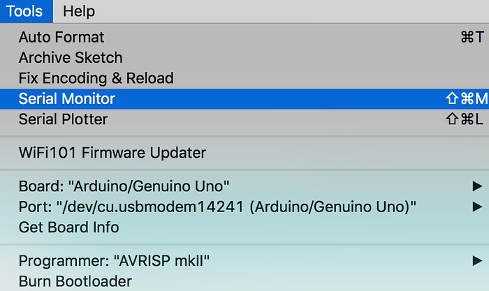
Once you have it wired up you should be able to use the Arduino Serial Monitor in the Arduino IDE to access the Module. Remember you’ll connect to the port the Arduino is on.
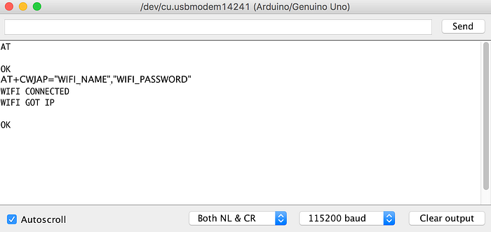
Next, make sure you choose “Both NL & CL” then adjust the Baud rate. My module was talking on 115200 baud but I’ve heard other models on 9600.
At this point, you should be able to send an “AT” command and get an “OK” response. WoHoo! you’re talking to the module.

Let’s play more. For this section I found its easier to prep your commands in a text editor then just copy and paste into the Serial Monitor.
Connect to your wifi by sending
AT+CWJAP=”WIFI_NAME”,”WIFI_PASSWORD”Be sure to put in your own wifi name and password
Connect to ThingSpeak
AT+CIPSTART=”TCP”,”api.thingspeak.com”,80
AT+CIPSEND=51
GET /update?key=XXXXXXXXXXXXXXXX&field1=55 \r\n
AT+CIPCLOSE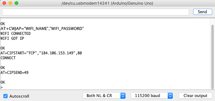
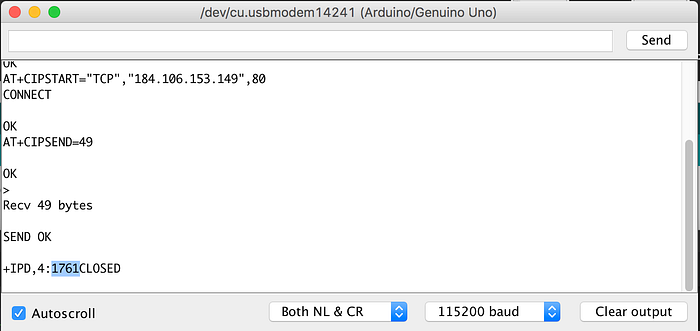
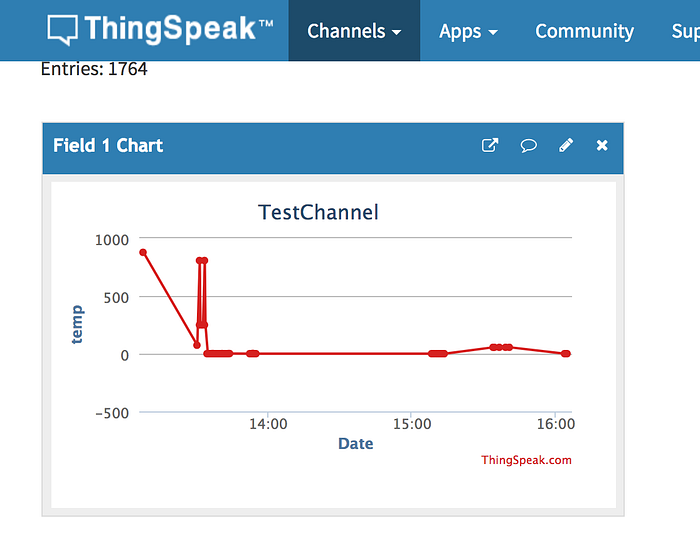
In this last image, I’ve highlighted the response from ThingSpeak. They return a counter and this was my 1761st message.
You should have received a response after the GET command. Check your ThingSpeak channel to see the data.
Note: AT+CIPSEND needs to be 2 more than the size of your GET line. I believe this is related to the Serial Monitor sending NL & CR.
Note: There needs to be a space after the URL in your GET and the new line characters, that tripped me up.
Accessing ESP8266 from Arduino Uno code
Now we’re ready for the normal flow. We’re going to write code for the Arduino to talk to the module. The wiring here will have the TX of the Uno connected to the RX on the module and the RX on the Uno talking to the TX on the module, but don’t do it yet. PROBLEM there’s only one serial on the Uno but we need it for debugging and also for the module. We can’t use one Serial for both. Thankfully we can use some code called SoftwareSerial to make a Virtual Serial port on the Arduino. This means that instead of connecting to the TX/RX we’ll connect to another pin set and have SoftwareSerial send commands to those pins instead.
Trying to wire into the Uno’s Serial TX/RX will block you from connecting the IDE to the UNO since it works over the USB Serial on the same pins.
Use SoftwareSerial library to connect the module through pins 10 & 11. Move the Module wires and be sure to remove the jumper wire that was between RESET and GND
Esp8266 | Arduino
 — — — — — — — — -
     RX | 11
     TX | 10
    GND | GND (same)
    VCC | 5v (same)
  CH_PD | 5v (same)
 GPIO 0 | None (same)
 GPIO 2 | None (same)
Note that White TX is in pin 10 and Grey RX is in Pin 11
Ok let’s look at some code
First, we need to set up the virtual serial for the module. We’ll include the library and define the variable
#include <SoftwareSerial.h>
#define RX 10
#define TX 11
SoftwareSerial esp8266(RX,TX);
From here on we’ll talk to the Module through “esp8266” and we’ll talk to the IDE through “Serial”. Let’s try it in our setup function
void setup() {
 Serial.begin(9600);
 esp8266.begin(115200);
 …
Note that we set the Serial connection to a 9600 baud rate and the esp8266 connection to a 115200 baud rate. Make sure to set your IDE Serial Monitor to the right baud and set the esp8266 value to the baud rate of the module you confirmed earlier.
Let’s add more and see if it’s working by passing in the same commands we did before
void setup() {
 Serial.begin(9600);
 esp8266.begin(115200);
 esp8266.println(command);
 esp8266.println(“AT+CWMODE=1”);
 esp8266.println(“AT+CWJAP=\”WIFI_NAME\”,\”WIFI_PASSWORD\””);
}
Sweet so hopefully that worked. If it didn’t the command may have timed out or failed. I found some code to help deal with that. The rest of the example is patterned off that source.
Basically, there’s a helper function called “sendCommand” that takes a command, a timeout value and the expected result as input. I also extracted the sensor data to its own function called, surprisingly, getSensorData. This has a simple random value in it now but will be replaced by actual sensor data in the final implementation
Putting it all together
OK ready for the whole code base? Note that the setup function below differs from the one above, just in case you were copy/pasting and didn’t catch that.
#include <SoftwareSerial.h>#define RX 10
#define TX 11String AP = "WIFI_NAME"; // CHANGE ME
String PASS = "WIFI_PASSWORD"; // CHANGE MEString API = "YOUR_API_KEY"; // CHANGE ME
String HOST = "api.thingspeak.com";
String PORT = "80";
String field = "field1";int countTrueCommand;
int countTimeCommand;
boolean found = false;
int valSensor = 1;SoftwareSerial esp8266(RX,TX);
void setup() {
Serial.begin(9600);
esp8266.begin(115200);
sendCommand("AT",5,"OK");
sendCommand("AT+CWMODE=1",5,"OK");
sendCommand("AT+CWJAP=\""+ AP +"\",\""+ PASS +"\"",20,"OK");
}void loop() {
valSensor = getSensorData();
String getData = "GET /update?api_key="+ API +"&"+ field +"="+String(valSensor);sendCommand("AT+CIPMUX=1",5,"OK");
sendCommand("AT+CIPSTART=0,\"TCP\",\""+ HOST +"\","+ PORT,15,"OK");
sendCommand("AT+CIPSEND=0," +String(getData.length()+4),4,">");
esp8266.println(getData);delay(1500);countTrueCommand++;
sendCommand("AT+CIPCLOSE=0",5,"OK");
}int getSensorData(){
return random(1000); // Replace with
}void sendCommand(String command, int maxTime, char readReplay[]) {
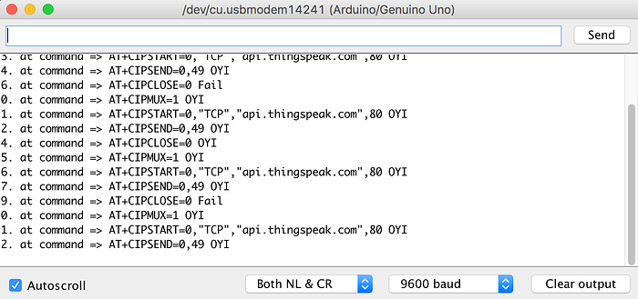
Serial.print(countTrueCommand);
Serial.print(". at command => ");
Serial.print(command);
Serial.print(" ");
while(countTimeCommand < (maxTime*1))
{
esp8266.println(command);//at+cipsend
if(esp8266.find(readReplay))//ok
{
found = true;
break;
}
countTimeCommand++;
}
if(found == true)
{
Serial.println("OYI");
countTrueCommand++;
countTimeCommand = 0;
}
if(found == false)
{
Serial.println("Fail");
countTrueCommand = 0;
countTimeCommand = 0;
}
found = false;
}
Head over to ThingSpeak to see your data
There ya go, You’ve got WiFi on your Arduino. Happy IoT-ing